| Name | Vortex air flotation | Size | According to your order |
| Brand Name | YOSUN | Power | According to your order |
| Place of Origin | Jiangsu, China | Color | Yosun standard or According to customer's requirement |
| Marketing Type | Hot Product 2024 | Feature | High hydraulic load with skimmer |
| Warranty | 1 Year | Function | SS removal BOD removal |
| Warranty of core components | 1 Year | Application | Wastewater Treatment |
| Productivity | 3000L/Hour | Capacity | 5-200m3/h |
| Weight (KG) | 1300 kg | Video outgoing-inspection | Provided |
| Material | According to your order | Machinery Test Report | Provided |
| Weight | 1.5-12000KG | Transport | According to your order |

What is Vortex air flotation ?
The vortex air flotation system is a wastewater treatment technology that removes grease, colloids, and suspended solids in sewage (especially petrochemical oily sewage).
The wastewater coagulates with PAC and PAM and then flows to the aeration zone. The hollow impeller aerator configured here rotates at high speed to form a vacuum zone in the water so that the air is pumped underwater and crushed into microbubbles under shear force. The solid pollutants in the sewage are combined with microbubbles. The buoyancy generated by the imbalance between the air-water combination and the density of water brings the solid pollutants to the water surface, and the scum on the water surface is scraped into the collection tank through a slag scraper. The purified sewage is discharged through the overflow weir.
Vortex air flotation machine working process(Video Description)

Basic structure of vortex concave air flotation system
How vortex air flotation works ?
The working principle of vortex air flotation is that the sewage, after dosing and coagulation, first enters the vortex equipped with The aeration area of the aerator, which is equipped with a patented unique aerator, uses hollow leaves at the bottom to The rapid rotation of the wheel creates a vacuum zone in the water, and the air above the water passes through The hollow pipe is pumped underwater, and the three shear forces generated by the rapid rotation of the impeller at the bottom The air is crushed into microbubbles. The microbubbles organically combine with the solid pollutants in the sewage. Together, they rise to the liquid surface. After reaching the liquid surface, solid contaminants rely on these microbubbles The support floats on the water, and the scum is scraped into the scum collection tank by a scum scraper.
The vortex air flotation machine mainly comprises a box, an aerator, a mud scraping system, etc., and does not require pressure-dissolved air, air compressors, circulation pumps, or other equipment.
Compared with the pressurized dissolved air flotation machine, the vortex concave air flotation machine has the following advantages:
(1) Low investment, low energy consumption, automatic slag discharge without noise, and convenient operation and management.
(2) Compared with traditional domestic pressurized dissolved air flotation systems, equipment such as dissolved air tanks, air compressors, high-pressure water pumps, and underground pipelines are omitted, and the energy consumption is 1/3~1/5 of conventional air flotation.
(3) This system can also remove grease, colloids, and fiber suspensions in sewage, reducing the sewage load such as SS and TP, and can significantly improve the color of the water quality.
Vortex Air Flotation Advantages
Strong adaptability to changes in water volume and quality
Low investment, economical, no pressure vessel, air compressor, and circulation pump required
Low energy consumption, low sludge moisture content, reduced sludge treatment costs
Reduced odor: The problem of sludge generating odor has been solved.
Dissolved air flotation Application Fields
Petrochemical, slaughtering, food.(Oil removal, SS reduction, COD reduction)
Printing and dyeing, textile, tanning.(Reduce SS, decolorization and COD)
Paper making, pharmaceutical.(Reduce SS and COD)
Final discharged water further improvment.(Phosphorus removal, SS reduction)
Reuse of reclaimed water.(Reduce SS and remove oil)
River, landscape water.(Reduce SS and turbidity)
New energy, precious metal recovery.(Reduce SS and remove fluorine)
Landfill leachate.(Reduce back-end biochemical load)
Surface treatment.(Heavy metals, SS reduction)

Dissolved air flotation technology parameter table
| Model | Capacity(m3/h) | Nozzle List(DN) | Dimension(mm) |
| Inlet | Outlet | Sludge | Vent | L
| L1 | L2 | W | W1
| H |
| RQAF-002 | 2 | DN50 | DN50 | DN80 | DN50 | 3500 | 2700 | 500 | 800 | 600 | 1600 |
| RQAF-003 | 3
| DN50 | DN50 | DN80 | DN50
| 3600 | 2800 | 500 | 900 | 600 | 1600 |
| RQAF-005 | 5 | DN80 | DN80 | DN80 | DN50 | 3850 | 3050 | 500 | 1000 | 600 | 1600 |
| RQAF-010 | 10 | DN100 | DN100 | DN100 | DN80 | 4500 | 3700 | 500 | 1100 | 600 | 1600 |
| RQAF-015 | 15 | DN125 | DN125 | DN100 | DN80 | 5400 | 4600 | 500 | 1200 | 600 | 1600 |
| RQAF-020 | 20 | DN150 | DN150 | DN100 | DN80 | 5900 | 5100 | 600 | 1300 | 600 | 1600 |
| RQAF-030 | 30 | DN150 | DN150 | DN125 | DN80 | 6700 | 5700 | 700 | 1500 | 600 | 1900 |
| RQAF-040 | 40 | DN200 | DN200 | DN150 | DN80 | 7500 | 6500 | 900 | 1800 | 600 | 1900 |
| RQAF-050 | 50 | DN200 | DN200 | DN150 | DN80 | 8200 | 7200 | 1000 | 2000 | 600 | 1900 |
| RQAF-060 | 60 | DN250 | DN250 | DN150 | DN80 | 8800 | 7800 | 1000 | 2200 | 600 | 1900 |
| RQAF-080 | 80 | DN250 | DN250 | DN200 | DN80 | 9800 | 8800 | 1200 | 2600 | 600 | 1900 |
| Model | Capacity(m3/h) | Power |
| Aerator(kw) | Skimmer(kw) | chemical reaction tank(kw) |
| RQAF-002 | 2 | 1.5 | 0.1 | 0.25 | 0.12 |
| RQAF-003 | 3
| 1.5 | 0.1 | 0.25
| 0.12 |
| RQAF-005 | 5 | 1.5 | 0.1 | 0.25
| 0.12
|
| RQAF-010 | 10 | 1.5 | 0.12 | 0.25
| 0.12 |
| RQAF-015 | 15 | 1.5 | 0.12 | 0.25
| 0.12 |
| RQAF-020 | 20 | 2.2 | 0.12 | 0.55
| 0.25 |
| RQAF-030 | 30 | 1.5*2 | 0.12 | 0.55
| 0.25 |
| RQAF-040 | 40 | 1.5*2 | 0.12 | 0.55
| 0.25 |
| RQAF-050 | 50 | 1.5*2 | 0.12 | 0.55
| 0.25 |
| RQAF-060 | 60 | 2.2*2 | 0.12 | 0.75
| 0.37 |
| RQAF-080 | 80 | 2.2*2 | 0.12 | 0.75
| 0.37 |
Dissolved air flotation outline drawing
| 1. Height adjustable overflow weir plate | 2. Scraper chain | 3. Flotation zone | 4. Return area |
| 5. water intake | 6. Return pipe | 7. Aeration zone | 8. Drainage area |
| 9. Overflow weir | 10. Outlet |
|
|
| Parts Name | Accessories Pictures | Parts Name | Accessories Pictures |
| Chain | 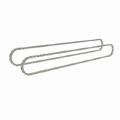 | Float level switch | 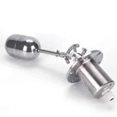 |
| Releaser | 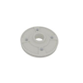 | Pressure Gauge | 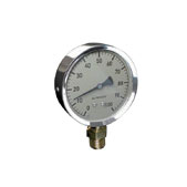 |
| Rubber Scraper |  | Chain wheel |  |

Dissolved air flotation product details
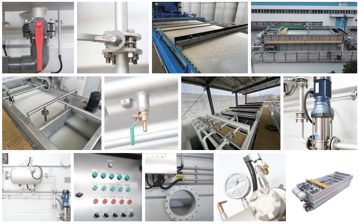
Effectiveness of equipment
Dissolved air flotation Effectiveness of equipment


Product application cases are continuously updated...
Name4


 注: 建议上传图片大小690px*460px


